Sidebar
23.3.5.3 Bézier curves project
With the CurveTo method of the Paint class, you can also draw curved lines whose curvature behaviour you specify. The CurveTo method uses a third-degree Bézier curve for drawing, which is determined by 4 points. Bézier curves with a degree higher than 3 are superfluous because complex curve arcs can be composed of partial arcs of Bézier curves of 1st - 3rd degree. Interesting, well-structured information on the definition and description of Bézier curves can be found, for example, at http://www.mathepedia.de/Bezierkurven.aspx and www.de.wikipedia.org/wiki/Bezierkurve.
In → Chapter 23.3.9, an attempt is made to develop an analytical description of a 2nd order Bézier curve from the geometric definition of a 2nd degree Bézier curve - for which there is no method in the Paint class. This derivation forms the theoretical basis for part of the present project, as some 2nd degree Bézier curves are drawn using the explicit parameter equations obtained and the methods of the Paint class.
Example 1
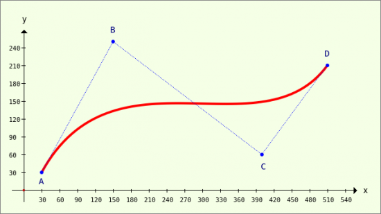
In the first example, a third-degree Bézier curve is drawn:
Figure 23.3.5.3.1: Modelled Bézier curve of the 3rd degree (4 points)
Points A and D determine the start and end points of the curve. The curvature behaviour is then determined by the position of points B and D → Figure 23.3.5.3.1. You may be surprised that only three points are specified in the documentation for the CurveTo method:
CurveTo ( X1 As Float, Y1 As Float, X2 As Float, Y2 As Float, X3 As Float, Y3 As Float )
This is correct because the current point is always understood as the starting point P0(X0|Y0) = A. This means that only the coordinates of points B, C and D are specified in the CurveTo method call.
This is the complete source code for drawing the image in → Figure 23.3.5.3.1:
[1] Public Sub PaintScriptBézier4Points()
[2]   Dim vP As Vector
[3]
[4]   GenerateNewPicture()
[5]   SetPictureBorder()
[6]   Paint.Begin(hPicture)
[7]     Paint.Translate(xTranslate, yTranslate)
[8]     Paint.Scale(xScale, yScale) ' +y ▲
[9]     DrawCoordinateSystem()
[10]
[11] '-- Vector with 8 elements, data type: real numbers (no complex numbers)
[12]     vP = New Vector(8, False)
[13] '-- A(30|30), B(150|250), C(400|60), D(510|210)
[14]     vP = [30, 30, 150, 250, 400, 60, 510, 210]
[15]     Paint.Brush = Paint.Color(Color.Red)
[16]     Paint.LineWidth = 4
[17]     Paint.LineCap = Paint.LineCapRound
[18]
[19]     Paint.MoveTo(vP[0], vP[1])
[20]     Paint.CurveTo(vP[2], vP[3], vP[4], vP[5], vP[6], vP[7])
[21]     Paint.Stroke()
[22]
[23] '-- Draw connecting lines A-B-C-D
[24]     Paint.Brush = Paint.Color(Color.Blue)
[25]     Paint.LineWidth = 1
[26]     Paint.Dash = [1, 1] '-- Dotted line (begin)
[27]     Paint.MoveTo(vP[0], vP[1])
[28]     Paint.LineTo(vP[2], vP[3])
[29]     Paint.LineTo(vP[4], vP[5])
[30]     Paint.LineTo(vP[6], vP[7])
[31]     Paint.Stroke()
[32]     Paint.Dash = [] '-- Dotted line (end)
[33]
[34] '-- Draw in points A, B, C and D
[35]     Paint.Arc(vP[0], vP[1], 3)
[36]     Paint.Arc(vP[2], vP[3], 3)
[37]     Paint.Arc(vP[4], vP[5], 3)
[38]     Paint.Arc(vP[6], vP[7], 3)
[39]     Paint.Fill()
[40]
[41] '-- Draw TEXTS
[42]     Paint.NewPath
[43]     Paint.Scale(1, -1)
[44]     Paint.Font = Font["Monospace, 11"]
[45]     Paint.Brush = Paint.Color(Color.DarkBlue)
[46]     Paint.DrawText("A", 25, -10)
[47]     Paint.DrawText("B", 145, -265)
[48]     Paint.DrawText("C", 398, -35)
[49]     Paint.DrawText("D", 505, -225)
[50]     Paint.Scale(1, -1)
[51]   Paint.End()
[52]
[53] End
Comment:
- The detailed descriptions of the procedures in lines 4 and 5 as well as in lines 7 to 9 can be found in → Chapter 23.3.3 'Drawing with Paint'.
- In line 12, a vector with eight elements is created whose data type is only real numbers. The eight elements contain the x and y coordinates of the four points A, B, C and D. The sequence corresponds to the order ABCD. In the third example, an alternative specification of the coordinates of the four points is presented.
- The Bézier curve of the 3rd degree - defined by the 4 points A, B, C and D - is drawn into the coordinate system using the instructions in lines 19 to 21. First the starting point is defined and then the Bézier curve is drawn in red from the starting point A to the end point D.
Note: Certain connecting lines and the support points B and C are only drawn in the instructions from line 23 onwards to clarify the position of all points in relation to the Bézier curve. The points A, B, C and D are drawn as a circle with a very small radius. Finally, the four points are labelled - but without specifying coordinates.
Example 2
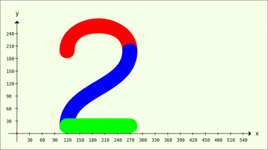
In this example, a number 2 is drawn from three Bézier curves - from two Bézier curves of the third degree and a line (Bézier curves of the first degree).
Figure 23.3.5.3.2: Number 2 from three Bézier curves
The source code for the procedure PaintScriptBezierNumber2() is given in full and commented:
[1] Public Sub PaintScriptBezierNumber2()
[2]   Dim PS, P1, P2, PE As New PointF
[3]   Dim vP, vQ As Vector
[4]   Dim fYOffset As Float
[5]
[6]   GenerateNewPicture()
[7]   SetPictureBorder()
[8]   Paint.Begin(hPicture)
[9]     Paint.Translate(xTranslate, yTranslate)
[10]     Paint.Scale(xScale, yScale) ' +y ▲
[11]     DrawCoordinateSystem()
[12]
[13] '-- Draw number 2
[14]     Paint.Scale(2, 2) ' +Zoom with a factor of 2
[15]     Paint.LineWidth = 18
[16]     fYOffset = Paint.LineWidth / 2
[17]   ' -----------------------------------------------------
[18]   ' Upper arch - red
[19]     PS.x = 60
[20]     PS.y = 90 + fYOffset
[21]     P1.x = 60
[22]     P1.y = 130 + fYOffset
[23]     P2.x = 135
[24]     P2.y = 130 + fYOffset
[25]     PE.x = 135
[26]     PE.y = 90 + fYOffset
[27]     Paint.LineCap = Paint.LineCapRound
[28]     Paint.Brush = Paint.Color(Color.Red)
[29]     Paint.MoveTo(PS.x, PS.y)
[30]     Paint.CurveTo(P1.x, P1.y, P2.x, P2.y, PE.x, PE.y)
[31]     Paint.Stroke()
[32]   ' -----------------------------------------------------
[33]   ' Centre curve - blue
[34]     vP = New Vector
[35]     vP = [60, 0, 60, 45, 135, 45, 135, 90]
[36]     vQ = New Vector
[37]     vQ = [0, 1, 0, 1, 0, 1, 0, 1]
[38]   ' vP = [60, 0 + fYOffset, 60, 45 + fYOffset, 135, 45 + fYOffset, 135, 90 + fYOffset]
[39]     vP = vP + fYOffset * vQ
[40]     Paint.Brush = Paint.Color(Color.Blue)
[41]     Paint.MoveTo(vP[0], vP[1])
[42]     Paint.CurveTo(vP[2], vP[3], vP[4], vP[5], vP[6], vP[7])
[43]     Paint.Stroke()
[44]   ' -----------------------------------------------------
[45]   ' Lower curve - green - 1st degree Bezier curve (straight line)
[46]     Paint.Brush = Paint.Color(Color.Green)
[47]     Paint.MoveTo(60, 0 + fYOffset)
[48]     Paint.LineTo(135, 0 + fYOffset) ' 1st degree Bezier curve
[49]     Paint.Stroke()
[50]   Paint.End()
[51]
[52] End
Comment:
- In line 14, a zoom factor of 2 is only used for drawing the number 2 using the Scale method for both coordinate directions, because the image was drawn correctly but too small in the first definitions for the 3 x 4 points per curve section.
- The offset in the y-direction - depending on the line thickness (line 15) - ensures that the number 2 is always on the x-axis as the base line → lines 17 and 18.
- For the upper arc of the number 2, the offset values in lines 19 to 26 are given directly to the 4 points PE, P1, P2 and PS together with the y-coordinate values.
- The cap shape for the ends of the lines to be drawn is specified in line 27 for all three curve sections.
- The upper curve arc is drawn using the instructions in lines 29 to 31.
- A new vector object is created for the middle curve section in line 34 and filled with 8 coordinates for 4 points in the following line using the inline vector.
- Line 39 shows a special feature: two vectors are added here, whereby the 2nd vector vQ is multiplied by the offset, which is only effective for the elements of vQ that are not zero. Alternatively, you could have used line 38.
- The third section of the curve is a straight line section with zero curvature and can be interpreted as a 1st degree Bézier curve → lines 47 and 48.
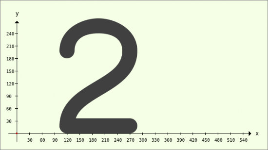
This is what the figure 2 looks like if only one colour is used for drawing:
Figure 23.3.5.3.3: Number 2 from three Bézier curves
Example 3
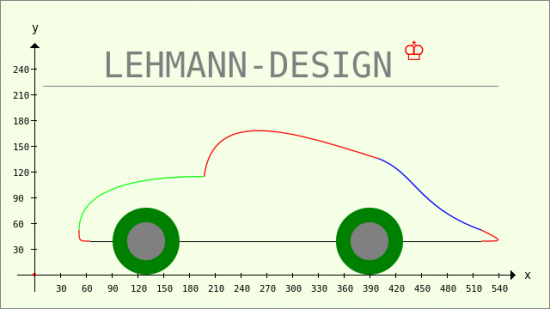
In this example, a graph is drawn that consists of several 3rd degree Bézier curves and other shapes (lines, circles). Points and connecting lines between the points are not drawn. Different colours are used to distinguish the individual curves. In addition to the other examples above, a text and a symbol are drawn:
Figure 23.3.5.3.4: Complex graphic with Bézier curves
The source code for the third example is also given in full and then commented:
[1] Public Sub PaintScriptBezierAuto()
[2]   Dim vP As Vector
[3]   Dim P0, P1, P2, P3 As New PointF
[4]   GenerateNewPicture()
[5]   SetPictureBorder()
[6]   Paint.Begin(hPicture)
[7]     Paint.Translate(xTranslate, yTranslate)
[8]     Paint.Scale(xScale, yScale) ' +y ▲
[9]     DrawCoordinateSystem()
[10]     Paint.Scale(1.3, 1.3) ' +Zoom with a factor of 1.3
[11]
[12]   ' CAR
[13]   ' -----------------------------------------------------
[14]   ' Front bumper
[15]     P0 = PointF(50, 30)
[16]     P1 = PointF(40, 30)
[17]     P2 = PointF(40, 30)
[18]     P3 = PointF(40, 40)
[19]     Paint.Brush = Paint.Color(Color.Red)
[20]     Paint.MoveTo(P0.x, P0.y)
[21]     Paint.CurveTo(P1.x, P2.y, P2.x, P2.y, P3.x, P3.y)
[22]     Paint.Stroke()
[23]   ' -----------------------------------------------------
[24]   ' Radiator cap
[25]     vP = New Vector
[26]     vP = [40, 40, 40, 80, 100, 88, 152, 88]
[27]     Paint.Brush = Paint.Color(Color.Green)
[28]     Paint.MoveTo(vP[0], vP[1])
[29]     Paint.CurveTo(vP[2], vP[3], vP[4], vP[5], vP[6], vP[7])
[30]     Paint.Stroke()
[31]   ' -----------------------------------------------------
[32]   ' Windscreen and roof
[33]     vP = New Vector
[34]     vP = [152, 88, 160, 152, 232, 128, 308, 104]
[35]     Paint.Brush = Paint.Color(Color.Red)
[36]     Paint.MoveTo(vP[0], vP[1])
[37]     Paint.CurveTo(vP[2], vP[3], vP[4], vP[5], vP[6], vP[7])
[38]     Paint.Stroke()
[39]   ' -----------------------------------------------------
[40]   ' Boot cover
[41]     vP = New Vector
[42]     vP = [308, 104, 340, 92, 344, 60, 400, 40]
[43]     Paint.Brush = Paint.Color(Color.Blue)
[44]     Paint.MoveTo(vP[0], vP[1])
[45]     Paint.CurveTo(vP[2], vP[3], vP[4], vP[5], vP[6], vP[7])
[46]     Paint.Stroke
[47]   ' -----------------------------------------------------
[48]   ' Rear bumper
[49]     vP = New Vector
[50]     vP = [400, 40, 420, 30, 420, 30, 400, 30]
[51]     Paint.Brush = Paint.Color(Color.Red)
[52]     Paint.MoveTo(vP[0], vP[1])
[53]     Paint.CurveTo(vP[2], vP[3], vP[4], vP[5], vP[6], vP[7])
[54]     Paint.Stroke()
[55]   ' -----------------------------------------------------
[56]   ' Bottom plate
[57]     Paint.AntiAlias = False
[58]       Paint.LineWidth = 1
[59]       Paint.Brush = Paint.Color(Color.Black)
[60]       Paint.MoveTo(400, 30)
[61]       Paint.LineTo(50, 30)
[62]       Paint.Stroke
[63]     Paint.AntiAlias = True
[64]   ' Front wheel
[65]     Paint.Brush = Paint.Color(Color.DarkGreen)
[66]     Paint.Arc(100, 30, 30)
[67]     Paint.Fill
[68]     Paint.Brush = Paint.Color(Color.Gray)
[69]     Paint.Arc(100, 30, 17)
[70]     Paint.Fill()
[71]   ' Rear wheel
[72]     Paint.Brush = Paint.Color(Color.DarkGreen)
[73]     Paint.Arc(300, 30, 30)
[74]     Paint.Fill()
[75]     Paint.Brush = Paint.Color(Color.Gray)
[76]     Paint.Arc(300, 30, 17)
[77]     Paint.Fill()
[78]   ' TEXT AND SYMBOL
[79]     Paint.NewPath
[80]     Paint.Scale(1 / 1.3, -1 / 1.3) ' Zoom = 1 and y-axis now with *positive* values downwards!
[81]     Paint.AntiAlias = False
[82]       Paint.Brush = Paint.Color(Color.Gray)
[83]       Paint.MoveTo(10, -220)
[84]       Paint.LineTo(540, -220)
[85]       Paint.Stroke()
[86]     Paint.AntiAlias = True
[87]     Paint.Font = Font["Monospace, 30"]
[88]     Paint.DrawText("LEHMANN-DESIGN", 80, -230) ' Text
[89]     Paint.Font = Font["Monospace, 30, bold"]
[90]     Paint.Brush = Paint.Color(Color.Red)
[91]     Paint.DrawText(String.Chr(9812), 430, -250) ' Crown symbol
[92]   Paint.End()
[93]
[94] End
Comment:
- In line 10, a zoom factor of 1.3 is used to draw the car in order to present the car at the optimum size.
- For the front bumper → lines 15 to 22, 4 individual points are declared and assigned suitable coordinate values. Instruction 20 is necessary!
- For all other Bézier curves, a vector is used that takes the coordinates of the 4 points that you need to draw the Bézier curve.
- In line 80, the zoom is cancelled again and at the same time the y-axis is set with a positive direction downwards (in relation to the drawing plane) so that the font is not displayed mirror-inverted. Pay attention to the negative y-value for all texts because of the translation in line 7 with the defined value of the y-shift!
- You are welcome to add further graphic elements such as windows, doors or spotlights, as the project with all examples can be found in the download area.


